![]()
![]()
![]()
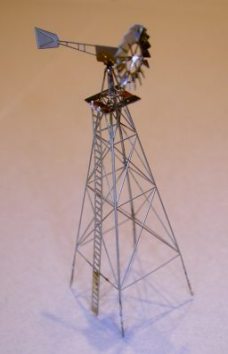
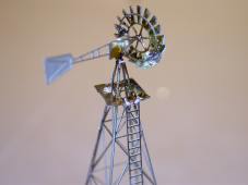
Instruction 3RWorks Aermotor 3RWorks kit Aermotor 8', 1:220
" Fine soldering iron, max. 25 W Before starting to work on your kit be aware of safety! Wear safety glasses during all cutting or grinding operations. Wear aspiration protection when handling with paints and solvents. The first step is to get an overview about the components of this kit. All parts are etched at one single sheet:
2. Now the tower needs to be bend. The sharp corner of a brass or aluminium or any other rectagular metal profile will do a good job here. Bending needs to be done to the inside of the tower. The inside of the tower is that side which was at the lettered side of the sheet. You also can identify the inside by a continous etching between the segments of the tower. A magnifier is a good aid in this case. The front side has very fine connections at the knot points (see pictures below). Start bending of all 3 corner by 25 to 30 degrees. Then do the final bend of 90°. 3. Apply a fine soldering line at the edge of the open side of the tower. 4. Put the platform over the top of the tower and solder to the tower. This operation can also be done with CA glue. 5. You can either use the right or the Aermotor to fix at the top. It is also possible to glue or solder both sides together. In this case you need to remove the vane shaft of one side. Fixing the aermotor on the top of the tower can be done either by soldering or gluing with CA. 6. For the vanes you have two choices: The easier one without support ring or the a bit more tricky one with support ring. For both version first widen the the center hole of the vanes to accept the shaft. Every single blades need to be bend. The standard vanes are finished now. 7. For the supported vanes you need now to insert the ring into the notches of the vanes. Now solder or glue both parts together. 8. Solder now your choice of vanes to the shaft of the Aermotor. 9. Solder the ladder to the tower and platform. Your Aermotor is now finished. The kits needs to be cleaned from flux and to be degreased to prepare painting. Then primer the kit. The colour of the paint to be appied finally can vary. Common are light grey tones, as usual corrosion protection paints are. Differnt colours are possible too, sometimes these windmills are re-painted by their owners just with the brand and type of paint they have available. You can improve your model by adding a thin wire to replicate the pump rod from the top of the Aermotor to the pump unit at the ground.
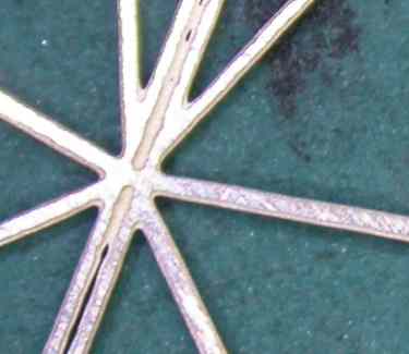
Below you see inside and outside of the tower. At the inside there is a continuous etching between each segments.
The outside has connections at the knots. Use a magnifier! Inside with continuous etching. Outside with connections.
The supported vanes. Platform and ladder |
 The following tools and material is required fort his kit:
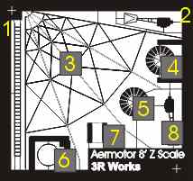 1 - Ladder
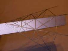 Bending of the tower.
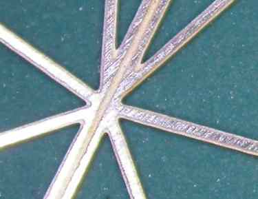

![]()
Powered by  http://www.3RWorks.com